


 INQUIRY
Description
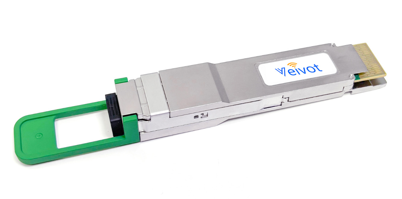
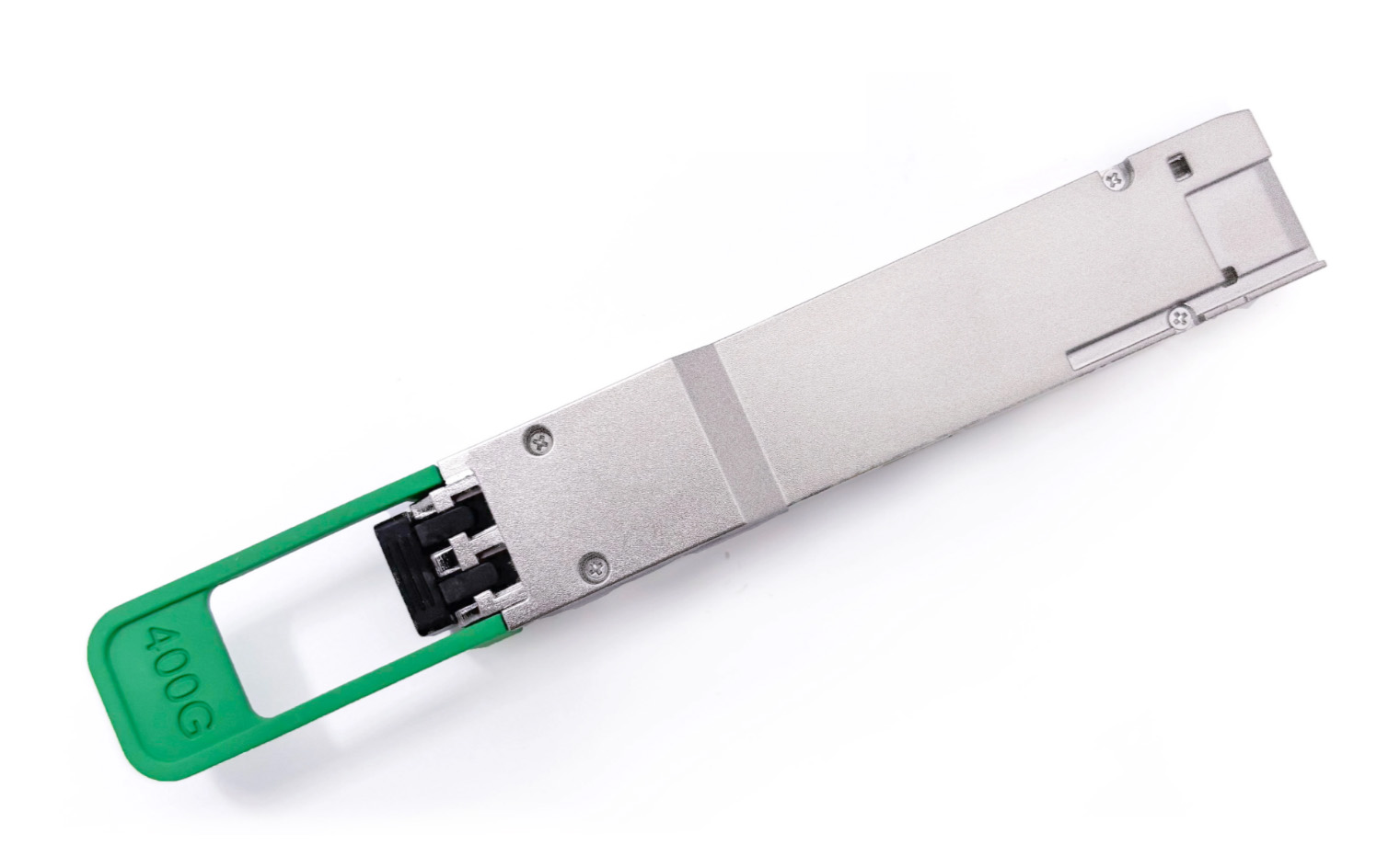
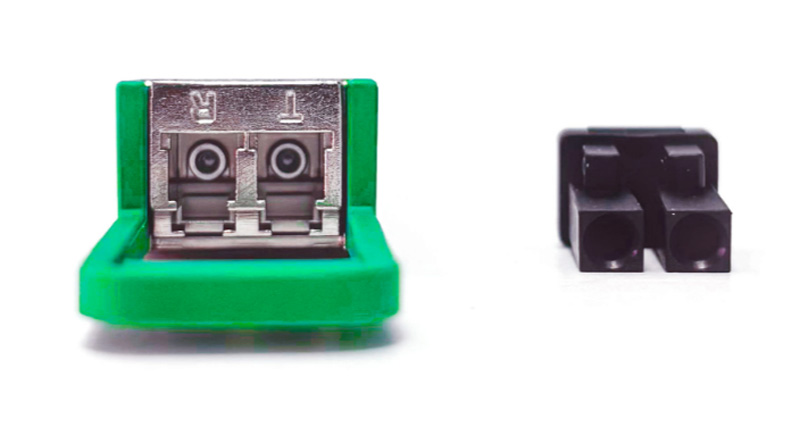
The 400GBASE-DR4 QSFP-DD is a 400Gb/s four-channel small form-factor pluggable double-density (QSFP-DD) optical transceiver that transmits data up to 2 kilometers over parallel single-mode fiber via a duplex LC connector. It converts eight 50Gb/s (PAM4) electrical input signals into four CWDM optical signals and multiplexes them into a single 400Gb/s optical transmission signal. Conversely, at the receiving end, the module optically demultiplexes the 400Gb/s optical input signal into four CWDM optical signals and converts them into eight 50Gb/s (PAM4) electrical output data signals. The four CWDM channels have center wavelengths of 1271 nm, 1291 nm, 1311 nm, and 1331 nm, and are primarily used for data center interconnects and 400G Ethernet applications. It complies with the IEEE 802.3bs standard, the 400GBASE-FR4 specification of the 100G Lambda MSA organization, and the 400GAUI-8/CEI-56G-VSR-PAM4 standard. The 400 Gigabit Ethernet signal is transmitted over four CWDM wavelengths. The multiplexing and demultiplexing of these four wavelengths are performed internally within the device.
Features
Compliant with 400G-FR4 Technical Specification rev 2.0 (100G Lambda MSA) and 400GBASE-FR4(IEEE802.3cu):
Compliant with IEEE 802.3bs standard: 400GAUI-8 electrical interface
Compliant with QSFP-DD MSA HW Rev 5.0; type 2 housing with duplex LC connector
Compliant with QSFP-DD CMIS Rev 4.0
Maximum power consumption 12 W
Case operating temperature 0°C to 70°C
Two wire serial Interface with digital diagnostic monitoring
Complies with EU Directive 2011/65/EU (RoHS compliant)
Class 1 Laser
Applications
400GBase-LR4 Ethernet
Switches and Routers
Data centers Interconnect
Optical Specifications
Parameter | Symbol | Min. | Typical | Max. | Unit | Notes |
Wavelength L0 | λC0 | 1264.5 | 1271 | 1277.5 | nm | |
Wavelength L1 | λC1 | 1284.5 | 1291 | 1297.5 | nm | |
Wavelength L2 | λC2 | 1304.5 | 1311 | 1317.5 | nm | |
Wavelength L3 | λC3 | 1324.5 | 1331 | 1337.5 | nm | |
Side Mode Suppression Ratio | SMSR | 30 | - | - | dB | |
Average Launch Power, each lane | AOPL | -3.3 | - | 3.5 | dBm | 1 |
Outer Optical Modulation Amplitude (OMAouter), each lane | TOMA | -0.3 | - | 3.7 | dBm | 2 |
Difference in launch power between any two lanes (OMAouter) | DP | - | - | 4 | dB | |
Launch Power in OMAouter minus TDECQ for ER ≥4.5dB, each lane | TOMA-TDECQ | -1.7 | - | - | dBm | |
Launch Power in OMAouter minus TDECQ for ER <4.5dB, each lane | TOMA-TDECQ | -1.6 | - | - | dBm | |
Transmitter and Dispersion Eye Closure for PAM4 (TDECQ), each lane | TDECQ | - | - | 3.4 | dB | |
TDECQ – 10*log10(Ceq), each lane | - | - | 3.4 | dB | ||
Average Launch Power of OFF Transmitter, each lane | TOFF | - | - | -20 | dBm | |
Extinction Ratio, each lane | ER | 3.5 | - | - | dB | |
Transmitter transition time | TT | - | - | 17 | ps | |
RIN17.1OMA | RIN | - | - | -136 | dB/Hz | |
Optical Return Loss Tolerance | ORL | - | - | 17.1 | dB | |
Transmitter Reflectance | TR | - | - | -26 | dB | |
Transmitter and Dispersion Eye Closure for PAM4 (TDECQ), each lane | TDECQ | - | - | 3.4 | dB | 3 |
Note 1: Average launch power, each lane (min) is informative and not the principal indicator of signal strength.
Note 2: Even if the TDECQ < 1.4 dB for an extinction ratio of ≥ 4.5 dB or TDECQ < 1.3 dB for an extinction ratio of < 4.5 dB, the OMAouter (min) must exceed this value.
Note 3: Transmitter reflectance is defined looking into the transmitter.
Receiver Optical Specifications
Parameter | Symbol | Min. | Typical | Max. | Unit | Notes |
Wavelength L0 | λC0 | 1264.5 | 1271 | 1277.5 | nm | |
Wavelength L1 | λC1 | 1284.5 | 1291 | 1297.5 | nm | |
Wavelength L2 | λC2 | 1304.5 | 1311 | 1317.5 | nm | |
Wavelength L3 | λC3 | 1324.5 | 1331 | 1337.5 | nm | |
Damage Threshold, each lane | AOPD | 4.5 | - | - | dBm | |
Average Receive Power, each lane | AOPR | -7.3 | - | 3.5 | dBm | 1 |
Receive Power (OMAouter), each lane | OMAR | - | - | 3.7 | dBm | |
Difference in receive power between any two lanes (OMAouter) | DR | - | - | 4.1 | dB | |
Receiver Reflectance | RR | - | - | -26 | dB | |
Receiver Sensitivity (OMAouter), each lane | SOMA | - | - | Max | dBm | 2 |
Stressed Receiver Sensitivity (OMAouter), each lane | SRS | - | - | -4.3 | dBm | 3 |
Conditions of stressed receiver sensitivity test | ||||||
Stressed eye closure for PAM4 (SECQ) | - | - | 3.4 | - | dB | |
SECQ – 10*log10(Ceq), lane under test (max) | - | - | 3.4 | dBm | ||
OMAouter of each aggressor lane | 1.5 |
Note 1: Average receive power, each lane (min) is informative and not the principal indicator of signal strength.
Note 2: Receiver sensitivity (OMAouter), each lane (max) is informative and is defined for a transmitter with a value of SECQ up to 3.4 dB.
Note 3: Measured with conformance test signal at TP3 for the BER = 2.4x10⁻⁴
Ordering Information
Part No. | Application | Data Rate | Laser Source | Fiber Type |
VV-QDD-FR4 | 400GBASE-FR4 | 400GB Ethernet | EML | Single Mode Fiber |
Email: sales@veivot.com Web: www.veivot.com