


 INQUIRY
Description
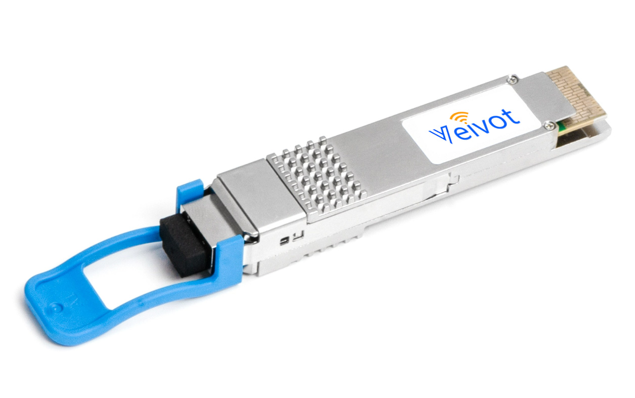
The 400GBASE-LR8 QSFP-DD features eight LWDM channels: 1273, 1277, 1282, 1286, 1295, 1300, 1304, and 1309 nm, each operating at 53.125 Gbps (PAM4), for a total bandwidth of up to 425 Gbps. It uses a duplex LC connector and can transmit over parallel single-mode fiber for distances up to 10 kilometers.
Veivot's VV-QDD-LR8 complies with the IEEE 802.3bs protocol and the 400GAUI-8/CEI-56G-VSR-PAM4 standards. Furthermore, the 400G LR8 is based on PAM4 modulation technology, QSFP-DD packaging, and DSP chip design. With these features, this 400G QSFP-DD transceiver is widely used in 400G telecommunications connections, data center interconnects (DCI), metropolitan area networks, long-haul transmission, and high-performance computing network applications. The 400G QSFP-DD LR8 optical module is ideal for data center applications such as Ethernet switching and routing, storage area networks, and high-performance computing. It is also suitable for other areas such as 5G mobile networks, high-speed video streaming, artificial intelligence, and cloud computing.
Features
Compliant with IEEE 802.3bs standard: 400GBASE-LR8 optical interface; 400GAUI-8 electrical interface
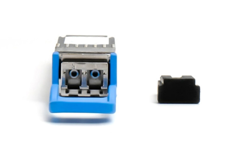
Compliant with QSFP-DD MSA HW Rev 5.0 with duplex LC connector
Compliant with QSFP-DD CMIS Rev 4.0
Case operating temperature 0°C to 70°C
Two wire serial Interface with digital diagnostic monitoring
Complies with EU Directive 2011/65/EU (RoHS compliant)
Class 1 Laser
Applications
400GBase-LR8 Ethernet
Switches and Routers
Data centers Interconnect
Optical Specifications
Parameter | Symbol | Min. | Typical | Max. | Unit | Notes |
Wavelength L0 | λC0 | 1272.55 | 1273.55 | 1274.54 | nm | |
Wavelength L1 | λC1 | 1276.89 | 1277.89 | 1278.89 | nm | |
Wavelength L2 | λC2 | 1281.25 | 1282.26 | 1283.27 | nm | |
Wavelength L3 | λC3 | 1285.65 | 1286.67 | 1287.68 | nm | |
Wavelength L4 | λC4 | 1294.53 | 1295.56 | 1296.59 | nm | |
Wavelength L5 | λC5 | 1299.02 | 1300.06 | 1301.09 | nm | |
Wavelength L6 | λC6 | 1303.54 | 1304.59 | 1305.63 | nm | |
Wavelength L7 | λC7 | 1308.09 | 1309.14 | 1310.19 | nm | |
Side Mode Suppression Ratio | SMSR | 30 | - | - | dB | |
Total Average Launch Power | AOPT | - | - | 13.2 | dBm | |
Average Launch Power, each lane | AOPL | -2.8 | - | 5.3 | dBm | 1 |
Outer Optical Modulation Amplitude (OMAouter), each Lane | TOMA | 0.2 | - | 5.7 | dBm | |
Difference in Launch Power between any two Lanes (OMAouter) | DT_OMA | - | - | 4 | dB | |
Launch Power in OMAouter minus TDECQ, each lane for ER >= 4.5dB | TOMA-TDECQ | -1.2 | - | - | dBm | |
Launch Power in OMAouter minus TDECQ, each lane for ER < 4.5dB | TOMA-TDECQ | -1.1 | - | - | dBm | |
Transmitter and Dispersion Eye Closure for PAM4 (TDECQ), each lane | TDECQ | - | - | 3.1 | dB | |
Average Launch Power of OFF Transmitter, each lane | TOFF | - | - | -30 | dBm | |
Extinction Ratio | ER | 3.5 | - | - | dB | |
RIN15.1OMA | RIN | - | - | -132 | dB/Hz | |
Optical Return Loss Tolerance | ORL | - | - | 15.1 | dB | |
Transmitter Reflectance | TR | - | - | -26 | dB | 2 |
Note 1: Average launch power, each lane (min) is informative and not the principal indicator of signal strength.
Note 2: Transmitter reflectance is defined looking into the transmitter.
Receiver Optical Specifications
Parameter | Symbol | Min. | Typical | Max. | Unit | Notes |
Wavelength L0 | λC0 | 1272.55 | 1273.55 | 1274.54 | nm | |
Wavelength L1 | λC1 | 1276.89 | 1277.89 | 1278.89 | nm | |
Wavelength L2 | λC2 | 1281.25 | 1282.26 | 1283.27 | nm | |
Wavelength L3 | λC3 | 1285.65 | 1286.67 | 1287.68 | nm | |
Wavelength L4 | λC4 | 1294.53 | 1295.56 | 1296.59 | nm | |
Wavelength L5 | λC5 | 1299.02 | 1300.06 | 1301.09 | nm | |
Wavelength L6 | λC6 | 1303.54 | 1304.59 | 1305.63 | nm | |
Wavelength L7 | λC7 | 1308.09 | 1309.14 | 1310.19 | nm | |
Damage Threshold, each Lane | AOPD | 6.3 | - | - | dBm | |
Average Receive Power, each Lane | AOPR | -9.1 | - | 5.3 | dBm | |
Receive Power (OMAouter), each Lane | OMAR | - | - | 5.7 | dBm | |
Difference in Receive Power between any two Lanes (OMAouter) | DR_OMA | - | - | 4.5 | dB | |
Receiver Reflectance | RR | - | - | -26 | dB | |
Receiver Sensitivity (OMAouter), each Lane | SOMA | - | - | -7.1 | dBm | 1 |
Stressed Receiver Sensitivity (OMAouter), each Lane | SRS | - | - | -4.7 | dBm | 2 |
Note 1: Receiver sensitivity (OMAouter), each lane (max) is informative and is defined for a transmitter with SECQ of 0.9 dB.
Note 2: Measured with conformance test signal at TP3 for the BER = 2.4x10⁻⁴
Ordering Information
Part No. | Application | Data Rate | Laser Source | Fiber Type |
VV-QDD-LR8 | 400GBASE-LR8 | 400GB Ethernet | EML | Single Mode Fiber |
Email: sales@veivot.com Web: www.veivot.com